


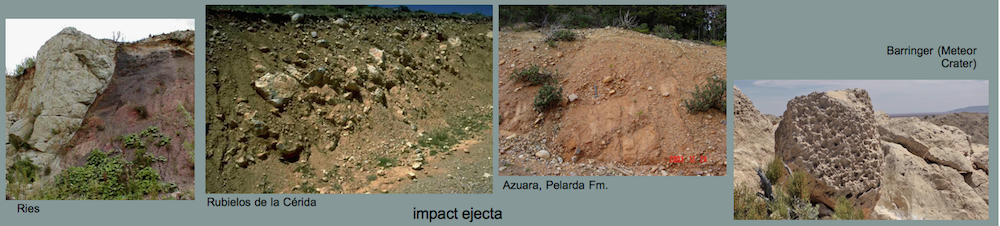


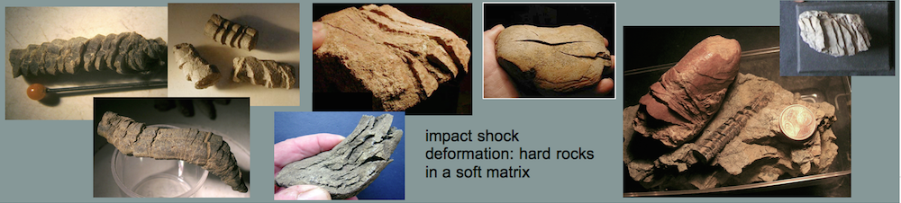


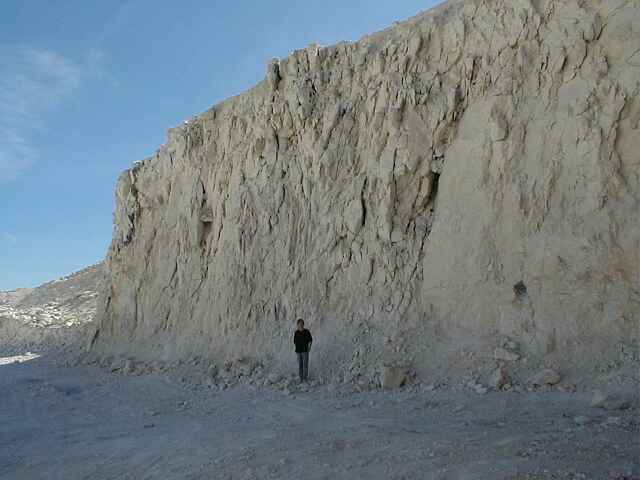
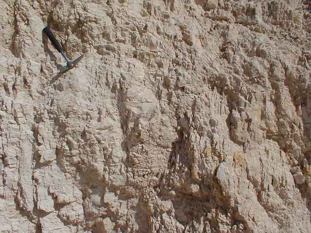
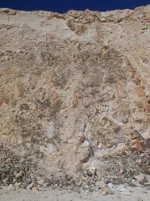
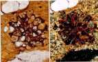
| Image A shows part of an extended megabreccia deposit in the southern central uplift of the Rubielos de la Cérida impact structure. Within a chaotic accumulation of limestone blocks and fragments, a large surface displaying prominent striae and polish occurs (hammer length 40 cm). Any relation to tectonic structures is clearly missing. It is assumed that the peculiar deformations formed in the highly compressive process of the central uplift development (modification stage of impact cratering). | 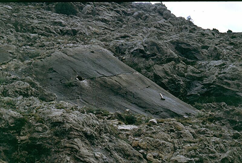 A A |
 B B |
An internal polish of strongly brecciated rocks is abundantly observed in the Rubielos de la Cérida structure; see Image B: mirror polish in a grit-brecciated megaclast of the Barrachina megabreccia. |
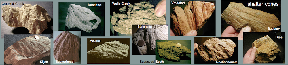
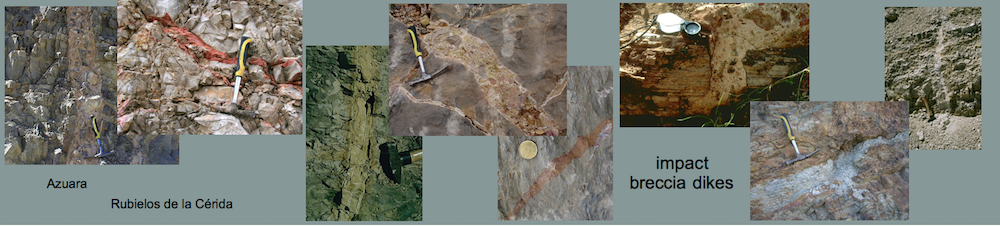
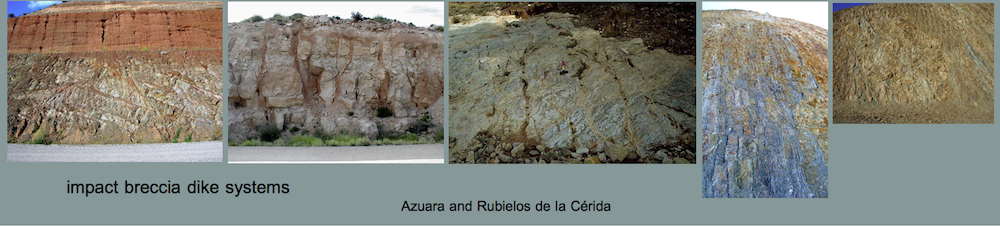
AZUARA IMPACT STRUCTURE (SPAIN) CURVED JOINT SETS: INDICATION OF IMPACT-INDUCED FRACTURING
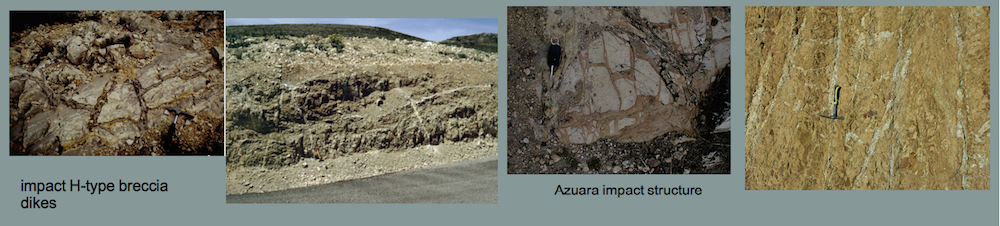
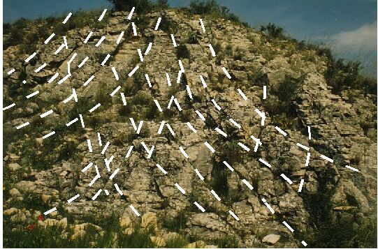
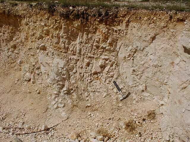
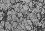
| The type locality of the peculiar curved joint pattern (Images A, B) has been found by H. Müller in the course of his diploma thesis mapping at the south-western ring of the Azuara impact structure (UTM coordinates, 684500/4555400, near Moneva) some 15 km from its center. The exposure shows fossiliferous Dogger limestones, which have undergone strong brittle fracturing. The joint sets under discussion are well exposed by their strong curvature. Two evidently conjugate sets with parallel strike form a system, which is nearly symmetrical to the vertical, and cut the rock into bars of approximately rhomboid shape. This often results in a rhomboid-within-rhomboid structure. Small displacements with slickensides parallel to dip have been observed to occur on the order of centimeters. | |
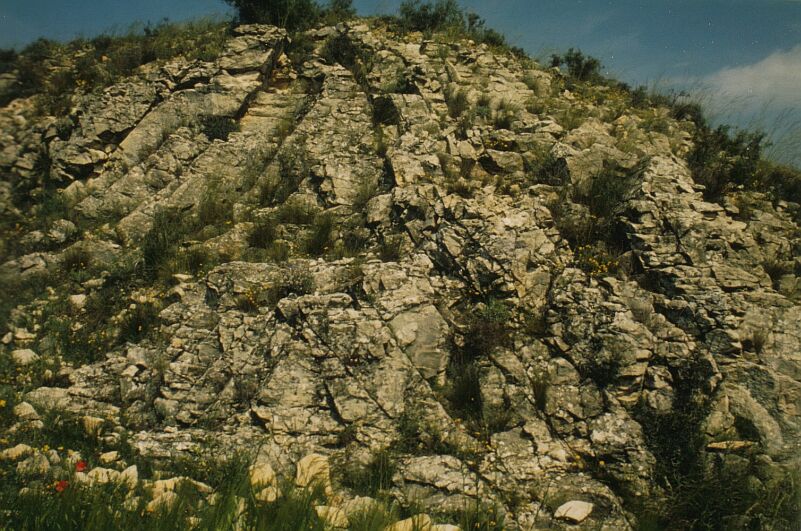 A A |
 B B |
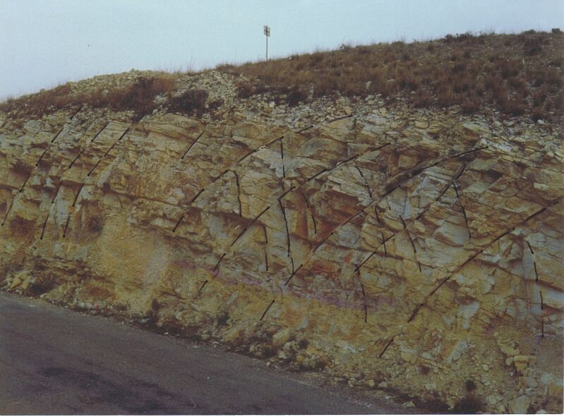
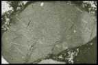
| Proceeding with field examinations, more joint systems with quite similar shape were found throughout the ring terrain of the Azuara structure. However, in contrast with the sets in Image A , the curved joints in Image C (south of Belchite) display counter convexity, and Image D (near Almonacid de la Cuba) shows the phenomenon on a smaller scale with a more irregular pattern. | |
 C C |
 D D |
 |
E: All locations are displayed in Image E where the strike directions of the curved sets are plotted. Although statistically only weakly exemplified, there is a trend of radial strike related to the center of the impact structure |
 Discussion. – In contrast to well established rhomboid structures resulting from the intersection of linear joints, strongly curved conjugate joint sets producing rhomboid-within-rhomboid structures are virtually unknown up to now. In a proceedings paper, pp. 257-263 (Image F), Müller and Ernstson excluded a relation to listric faulting, a formation by sedimentational and diagenetic processes, and presented a model of a dynamic formation which considers the modulation of running fractures in the impact cratering process. According to this model, the stress field of the shock-driven excavation flow combines with the stress field of the rising rarefaction pulse to a time-varying stress field causing the propagation of fractures along curved paths. Such a process is well known in experimental fracture mechanics: The modulation of a running fracture by ultra-sonic waves produces an undulating fracture surface.In our paper, we compute and show that in the early (excavation) stage of the impact cratering process, the conditions of the formation of curved conjugate joint sets can be met locally and during a short period of time.The model is not only consistent with the Azuara observations (radial strike with respect to the center, convex and concave curvature, different radii of curvature, rhomboid-within-rhomboid structures) but also predicts curved joint sets to belong to the regular structural inventory of impact craters. Discussion. – In contrast to well established rhomboid structures resulting from the intersection of linear joints, strongly curved conjugate joint sets producing rhomboid-within-rhomboid structures are virtually unknown up to now. In a proceedings paper, pp. 257-263 (Image F), Müller and Ernstson excluded a relation to listric faulting, a formation by sedimentational and diagenetic processes, and presented a model of a dynamic formation which considers the modulation of running fractures in the impact cratering process. According to this model, the stress field of the shock-driven excavation flow combines with the stress field of the rising rarefaction pulse to a time-varying stress field causing the propagation of fractures along curved paths. Such a process is well known in experimental fracture mechanics: The modulation of a running fracture by ultra-sonic waves produces an undulating fracture surface.In our paper, we compute and show that in the early (excavation) stage of the impact cratering process, the conditions of the formation of curved conjugate joint sets can be met locally and during a short period of time.The model is not only consistent with the Azuara observations (radial strike with respect to the center, convex and concave curvature, different radii of curvature, rhomboid-within-rhomboid structures) but also predicts curved joint sets to belong to the regular structural inventory of impact craters. |
|
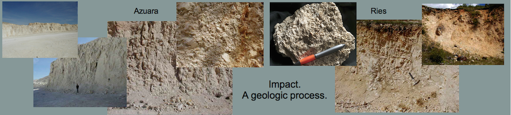
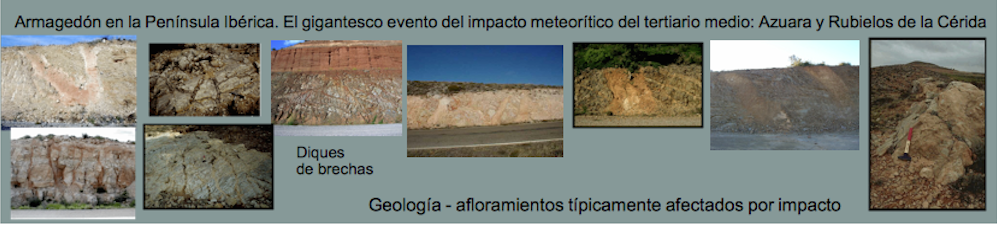
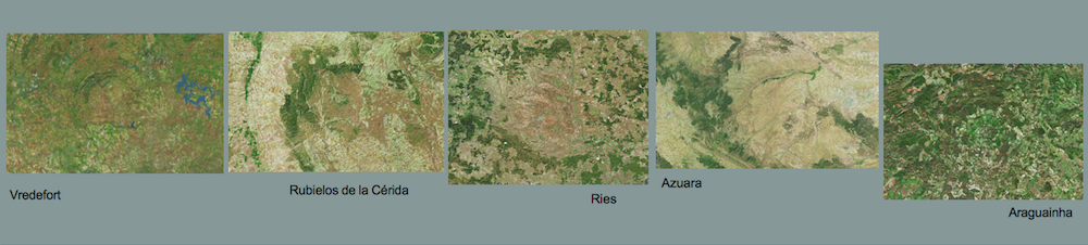
Azuara impact structure (Spain), Ries impact structure (Germany): impact as a geologic process
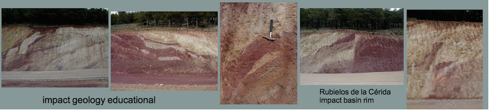
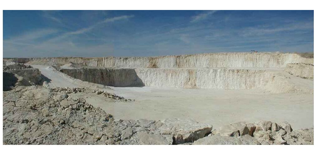
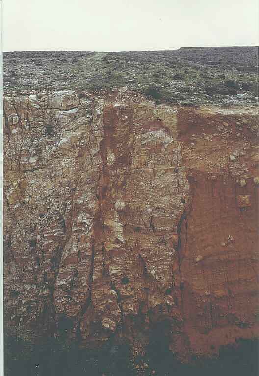
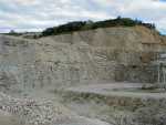
| A few kilometers outside the northern ring of the Azuara impact structure near Belchite, a handful of isolated large blocks of Jurassic limestones emerge from the post-impact Upper Tertiary Ebro basin sediments. Quarrying in these blocks has enabled instructive insight into the drastic impact deformations experienced by very large rock volumes. | |
 A A |
 B B |
| Image A shows part of a large quarry located at UTM coordinates 0687000, 4583000. The visible length in the image is roughly 300 m. The limestones are drastically destroyed through and through to form a more or less continuous breccia displaying grit (gries) brecciation and mortar texture (see Images B – E). | 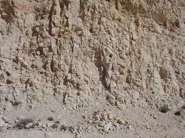 C C |
 D D |
 E E |
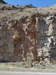
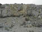
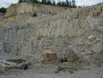
| Comparable strong and continuous deformations (Images F, G) can be observed in a limestone quarry located in another block at UTM coordinates 0683000, 4583000. | |
 F F |
 G G |
| H and I Ries impact structure; Iggenhausen quarry | |
 H H |
 I I |
| Comment: The Azuara region and the Jurassic limestones underwent Alpidic tectonics with some folding and block faulting, but we emphasize that Alpidic tectonics can not possibly have caused these disastrous deformations over hundreds of meters. Impact cratering is the only reasonable process to have produced this impressive geologic scenario, and the same deformations are well known to occur in large allochthonous limestone megablocks ejected from the 25km-diameter Ries impact structure (Germany) (Images H, J; Iggenhausen quarry).We suggest that those geologists from the Zaragoza university and the Center of Astrobiology (Madrid) vehemently refusing an Azuara impact visit these highlighting outcrops. Since they like to contrast the Azuara structure with the Ries crater (see their MAPS paper referred to in the Controversy section), they will get a lot of illustrative material.There is one more point we want to refer to. As already said, impact is the only reasonable geologic process that explains these desastrous and voluminous deformations. In other words, there’s actually no need for the well documented strong shock effects in Azuara polymictic breccias to establish Azuara as an impact structure (see below in the Archives and http://www.impact-structures.com/impact-spain/the-azuara-impact-structure/shock-effects-shock-metamorphism-in-rocks-from-the-azuara-impact-structure/ ). The outcrops under discussion here are as well a convincing proof.Usually, the impact nature of a structure under discussion is established by the occurrence of shock metamorphism. Reasonably, it is argued that there are no endogenetic processes known to produce, e.g., diaplectic glass or planar deformation features (PDFs) in quartz. Likewise, we argue that there are no endogenetic geologic processes known to have catastrophically destroyed the Jurassic limestones near Belchite. Therefore, geologists should be aware of their competence to establish in some cases an impact structure from pure field evidence. The time has come to give up the very limited point of view of some impact researchers that TEM analyses of PDFs or geochemical signature of the projectile are the ultimate requirement for establishing an impact structure. |
|
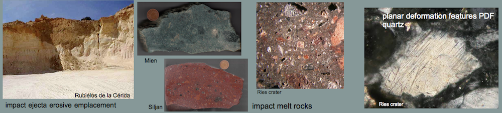
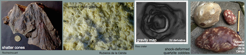
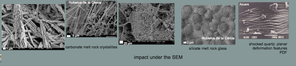
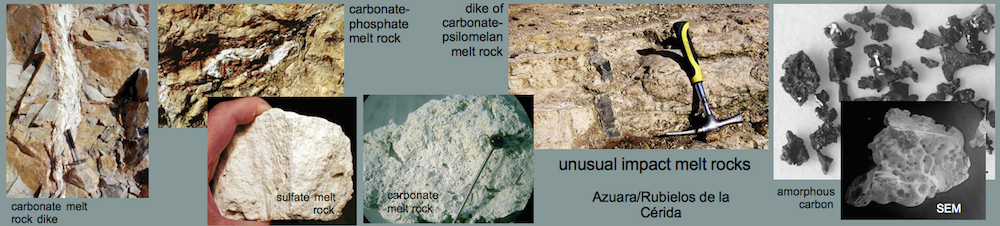
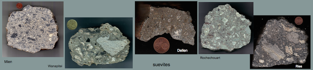
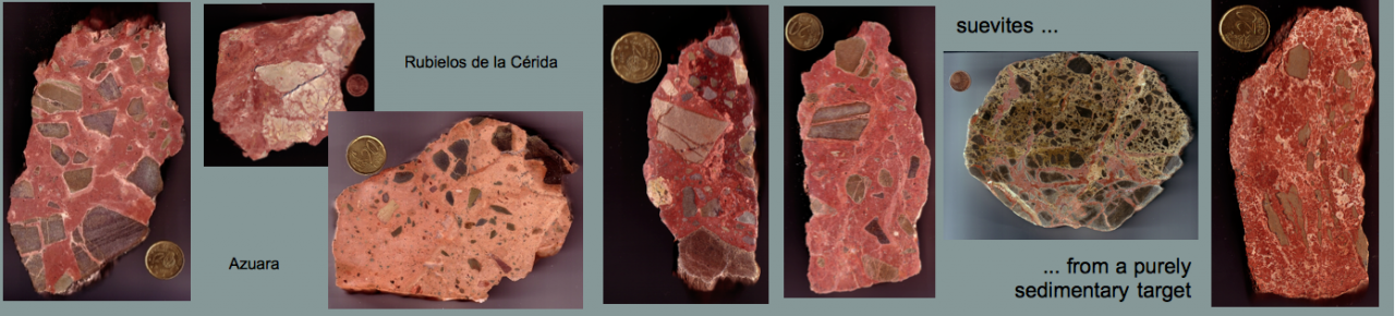
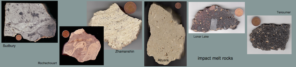
Rubielos de la Cérida impact structure (Spain): impact melt glass from the central uplift
 A A |
 B B |
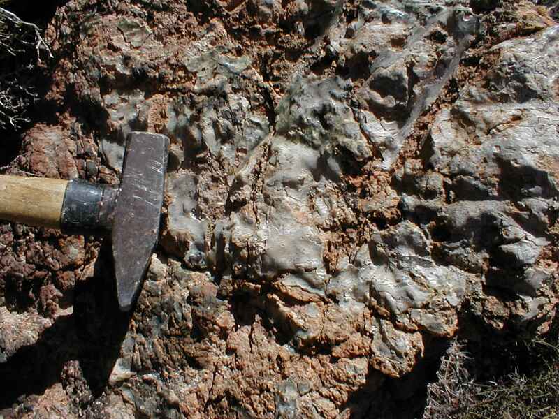
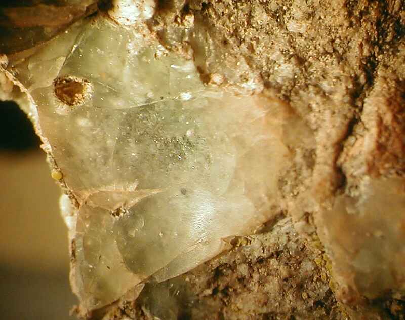
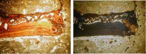
| The glass shown in A, B (B: the field is 14 mm wide) is coating a sandstone exposed in the central uplift of the Rubielos de la Cérida impact structure. The glass has a greenish to whitisch color and is transparent to milky. In thin section (C, D (xx nicols) – the field is 6 mm wide), the sandstone shows heavily damaged, and intense cataclastic flow texture is observed to merge with the glass. Quartz grains are strongly fractured and show multiple sets of planar fractures (PFs) and planar deformation features (PDFs). | |
 C C |
 D D |
| Interpretation: Despite the occurrence of shock features in the sandstone, the glass probably did not form by shock melting. We suggest frictional melting by extreme dynamic metamorphism in the impact event (excavation or – more probably – modification stage when the uplift formed) and the glass to be pseudotachylite. Temperatures in excess of 2,000 °C were probably required for the homogenization of this glass (David Griscom, pers. com.). The location of this spectacular exposure of the glass-bearing sandstone remains secret for the moment in order to prevent it from destruction by rock hunters. |
|
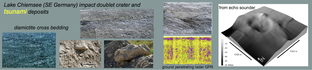
Rubielos de la Cérida impact structure, Spain: at the crater floor
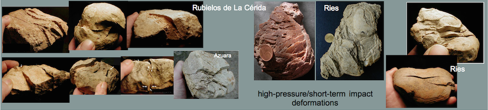
This peculiar fold is exposed in a region of an extended megabreccia near the village of Barrachina in the Rubielos de la Cérida impact structure. The fold is portrayed by a competent, however heavily brecciated Lower Tertiary limestone layer. The core of the fold is a pulp of nearly pulverized carbonate rock without any regular internal structure. Only a few limestone fragments are preserved.
Interpretation: The exposure is assumed to be located at or near the crater floor of the Rubielos de la Cérida impact structure (for more details see:
where giant rock masses moved in the excavation and modification stage of impact cratering to form the now exposed megabreccia. The fold is interpreted to be the result of a high-pressure injection of extremely brecciated material from below. A tectonic origin of this peculiar structure is hardly to understand. Local geologists (from the Zaragoza university and the Center of Astrobiology, Madrid) suggest collapse by dissolution of gypsum to have produced the megabrecciation – need we comment?
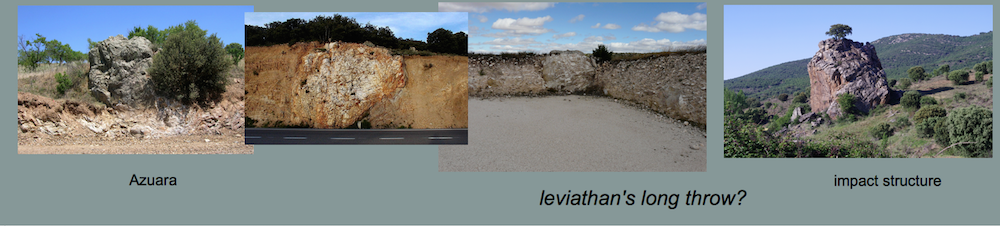
Azuara impact structure (Spain) – Ries impact structure (Germany)
Shortly after the impact …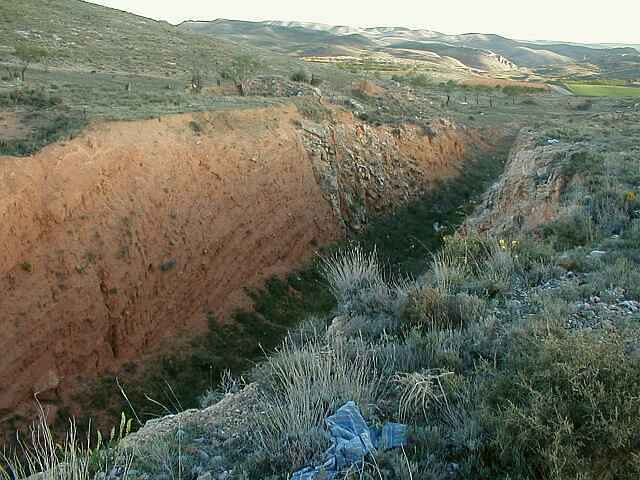 A A |
|
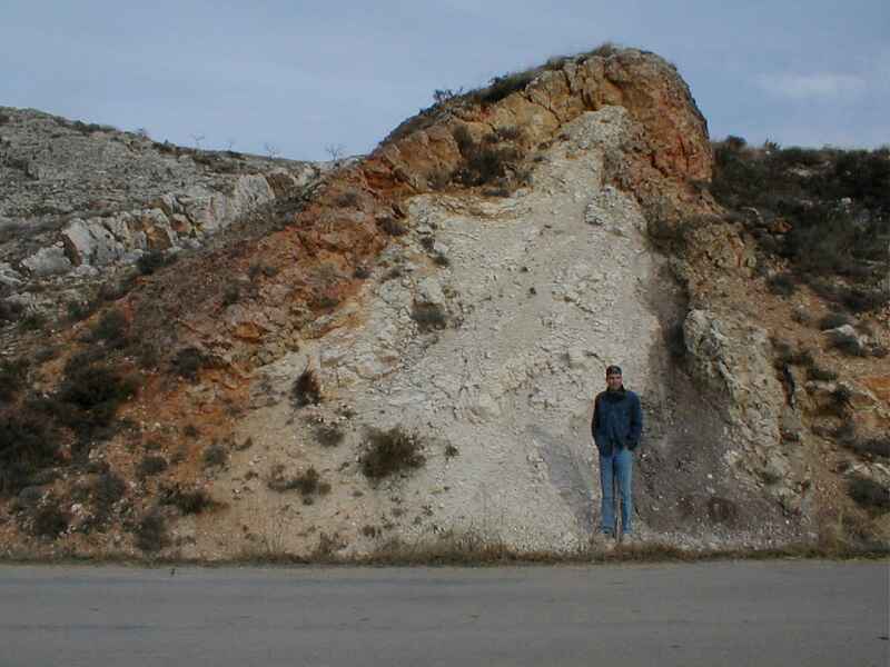
| The exposure in image A (details in B, C) results from the construction of an irrigation channel and is located near Blesa village about 14 km from the center of the Azuara impact structure. | |
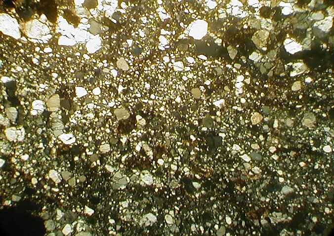
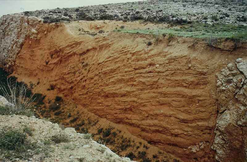 B BThe channel cuts through highly fractured and brecciated Liassic limestone megablocks in sharp and steep contact with well-bedded Tertiary sands. Near the contacts, a few disintegrated limestone blocks are floating in the sands. The sand is composed of predominantly calcite and quartz grains and some altered glass fragments. In thin section (D, plane polarized light; the field is 1 cm wide), the quartz grains show to be mostly sharp-edged indicating fragmentation and short transport. |
Many quartz grains display shock features like multiple sets of planar fractures (PFs) and multiple sets of planar deformation features (PDFs). |
| Interpretation: The peculiar contact between the sands and the overhanging and highly fractured rocks gives evidence of an obviously sudden and very short-term depositional process. The highly brecciated and partly overhanging flanks of the limestone megablocks would not have survived any substantial period of time, and faults can basically be excluded. Therefore, we suggest that the outcrop reflects the earliest phase of the post-impact sedimentation at the crater floor shortly after the impact. In some respects, the sandy unit may be compared with the so-called «graded unit» which has been found as a 17 m core section in the research borehole Nördlingen 1973 in the Ries impact structure (Germany). The «graded unit» occurs within the crater between the suevite impact breccia and aquatic sediments, and it is assumed to be the result of a single-phase sedimentation. Alternative processes consider airfall of ejected impact material or a turbidity current-type transport mechanism in water or steam. Both are possible explanations also for the deposition of the sandy unit in the Blesa irrigation channel, which is currently investigated in more detail. |
|
Ries impact structure (Germany); Azuara and Rubielos de la Cérida impact structures (Spain)
|
|||
|
|||
 C CAguilón; Jurassic limestones (Azuara structure). Note the bedding in the base speaking against a tectonic fault.
|
 D Dnear Santa Eulalia; Muschelkalk limestones (Rubielos de la Cérida structure). Note the block of bedded limestone floating in the highly brecciated material. |
||
| In all three cases, a tectonic interpretation of the layering offers considerable difficulties. | |||
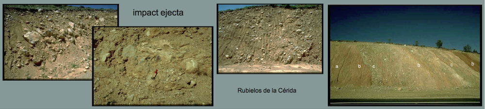
Rubielos de la Cérida impact structure (Spain)
|
|||
|
|||
.jpg)
.jpg)
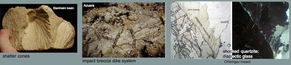
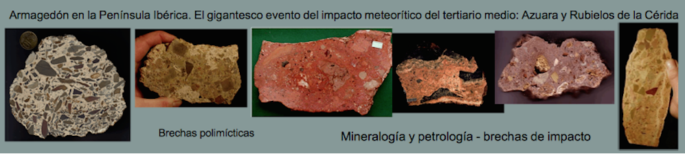
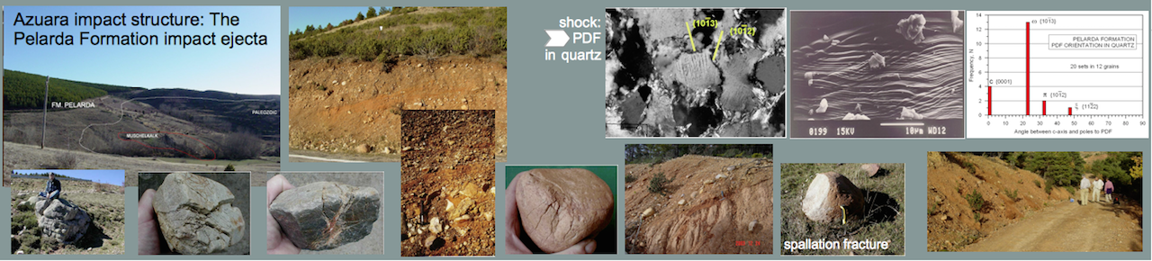
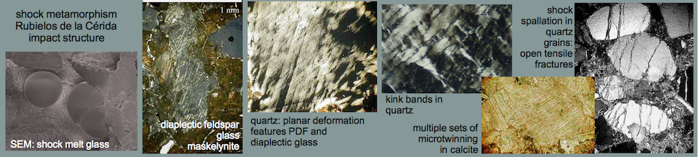
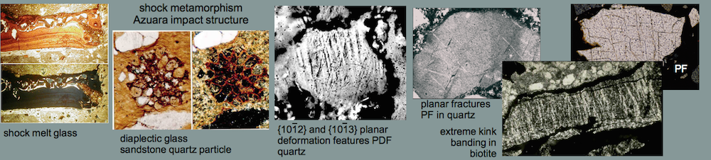
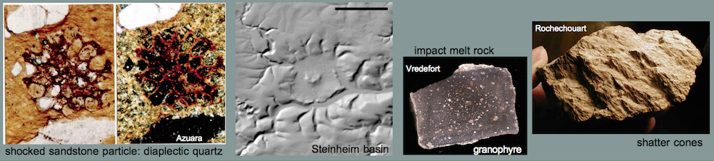
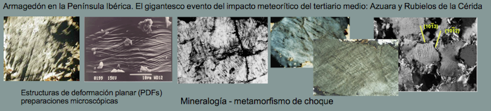
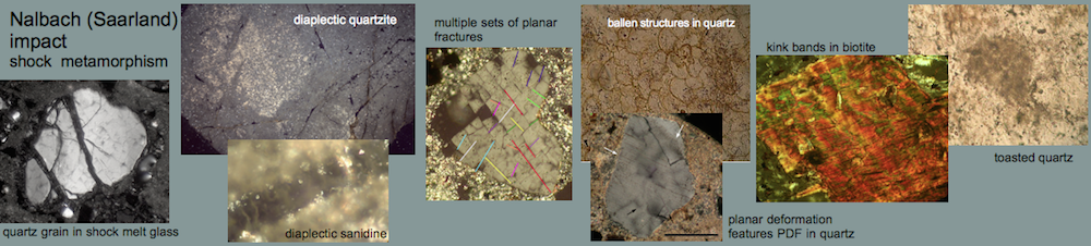
Azuara impact structure, Spain: shock metamorphism
Highly shocked polymictic dike breccia (near Santa Cruz de Nogueras, 30660971E, 4553223N). Typical shock effects in the breccia are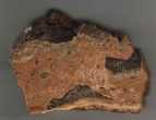 |
||||
 A A
|
||||
 BB: Diaplectic glass; photomicrograph of a sandstone fragment completely transformed to diaplectic quartz; plane polarized light and xx nicols. Note that there are a few holes in the thin section not to be confused with diaplectic quartz grains. The field is 600 µm wide. BB: Diaplectic glass; photomicrograph of a sandstone fragment completely transformed to diaplectic quartz; plane polarized light and xx nicols. Note that there are a few holes in the thin section not to be confused with diaplectic quartz grains. The field is 600 µm wide.
C: Planar deformation features (PDFs) in quartz grains; sandstone fragment from the shocked breccia. Photomicrograph, plane polarized light; the field is 800 µm wide. Note the large number of grains showing PDFs, their high density, the small spacing and the multiple sets. Up to five sets of different PDF orientation per grain have been observed in the dike breccia.
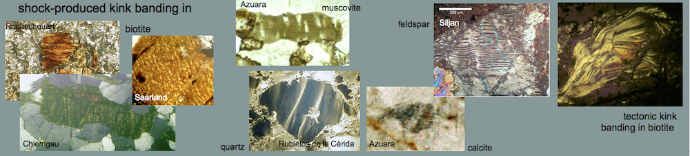
D: Planar fractures (PFs; cleavage) in quartz. Photomicrograph, xx nicols; the field is 450 µm wide. Note that at least six sets of different orientation can be observed. Cleavage in quartz is very uncommon in tectonically deformed quartz. In rare cases, rhombohedral fracturing is observed to occur in rocks which underwent strong regional metamorphism. In rocks from impact structures, PFs in quartz belong to the regular shock inventory. E: Kink bands in biotite from the shocked polymictic breccia. Photomicrograph, crossed nicols; the field is 840 µm wide. – Although kink bands can form under static conditions of strong regional metamorphism, the high frequency of the kink bands shown here, their narrow width, and their high kink-angle asymmetry point to shock deformation. The shock-metamorphic effects shown here correspond to a broad range of shock pressures. The melt glass, however, shows that parts of the breccia must have experienced shock peak pressures exceeding 500 kbars (50 GPa).
|
|
|||
 D
D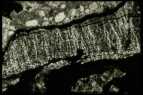 E
ERubielos de la Cérida impact structure, Spain:
A
B
C
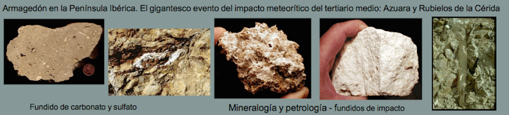
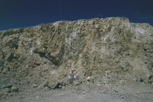
Rubielos de la Cérida impact structure, Spain:
Part of a large (some 300 m size) quarry exposing limestones (Muschelkalk Fm.) drastically destroyed through and through (A).
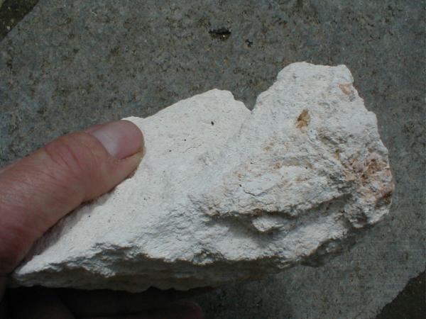
Within the completely brecciated rocks (displaying gries brecciation and mortar texture), white blocks (up to cubic-meter size) of carbonate material (B) are intercalated.
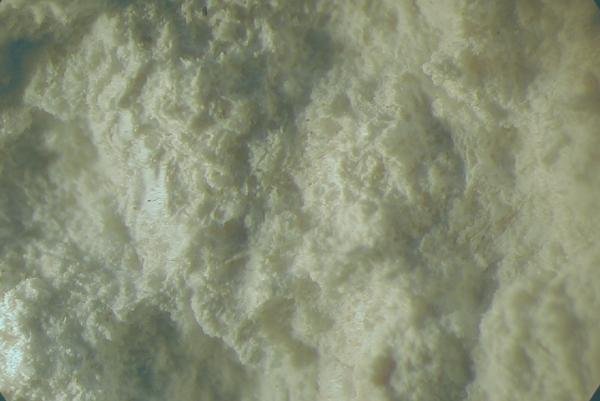
The low-density, highly porous material shows a distinct vesicular texture (C – the field is 7 mm wide).
Interpretation: A compressive strength of perhaps 150 – 200 MPa (= 1.5 – 2 kbar) for these massive and dense Muschelkalk limestones assumed, they must have experienced pressures clearly exceeding these values not only locally but throughout the huge volume. Whereas a tectonic origin can be excluded without any doubt, deformations like that are expected to occur in the cratering process (excavation and/or modification stage) of large impact structures. The intercalated white vesicular material is considered to be the relics from decarbonization and/or carbonate melt produced by shock or strong frictional heating.